Chap#2 An
Introduction to the Pentium Microprocessor
Objective
-
Real Mode and Protected
Mode Operation
-
Register Set of Pentium
-
Addressing Capabilites
and Data Type
-
Addressing Mode and Instruction
Type
-
Interrupt
-
Hardware, Software of
8088
-
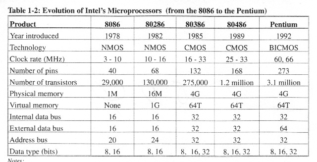
Difference of 8086 and
80286, 80386, 80486 and Pentium Microprocessor
2.1
Introduction
-
Pentium offers compatibility
with 80x86 machine with new architectural improvement
2.2
Real Mode and Protected Mode Operation
-
Addressing Space (Ref
Tab)
-
80286 ~ Pentium operated
in
1)
Real Mode (run in DOS, Like very first 8086)
2)
Protected Mode (run in Window OS) support for
* Multitasking
* Virtual memory addressing
* Memory management
* Protection
2.3
The Software Model of the Pentium (Fig 2.1)
-
4 Data Register : EAX,
EBX, ECX, EDX
-
5 Pointer/Index Register
* ESP : Stack Pointer
* EBP : Base Pointer
* ESI : Source Index
* EDI : Destination Index
* EIP : Instruction Pointer
-
6 Segment Register : to
access memory and I/O
-
1 Flag Register : to indicate
result of ALU Instruction
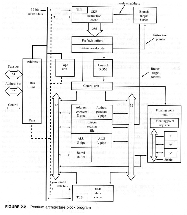
2.4
A Functional Description of the Pentium
-
Pentium Architecture (Fig
2.2)
-
2 pipeline U and V for
Executing 80x86 Instruction
-
A Floating Point Unit
for Executing 80x87 Instruction
-
U and V pipe can exe at
same time
-
32 Bit Address Bus
-
64 Bit Data Bus
-
Bus Unit perform burst
read and writes of 32 Byte to memory
-
Bus cycle pipeline , allows
2 bus cycle at same time
-
8KB Instruction Cache
provide quick access
-
Branch target buffer and
Prefetch buffer work together
-
Prefetch buffer copy 32
Byte code in 1 clock
-
Use branch prediction
to maintain a steady flow of instruction into the pipelines
-
8KB Data Cache (separate)
-
Both Code and Data cache
may be enable/disable with H/W or S/W
-
TLB (Translation Lakeside
Buffer) which converts logical address into physical addresses when virtual
memory is employed
-
Used U and V pipe , one
FP instruction may be execute at a time
2.5
Pentium Processor Register
-
Real Mode (virtual 8086)
address bus 20 Bit
-
Segment Register :
* CS, DS, SS, ES, FS, GS are all 16 Bit register
* Real Mode Segment = 2^16 = 64 KB
* Generating 20 bit address (Fig 2.3)
* In Protected Mode
The segment register are use as selector
that point to predefined segment descriptors
-
General Purpose Register
:
AX, BX, CX, DX, BP, SI and DI
have some specific role
* Accumulator(AX) is used in mul & div operation
and I/O port
* Count Register (CX) use as counter in loop operation
CL use as counter in shift/rotate operation
* Data Register (DX) is used in mul & div operation
and I/O pointer
* Source Index (SI) & Destination Index (DI)
are used as pointer in string operation
* Pentium operated in real mode
it register size is 16 bit
but can take 32 bit , by "operand size prefix 66H
* Example 2.1 (by MASM)
Distance : 93,000,000 miles (Sun to Earth)
Light Speed : 186,000 miles/sec
Determine Time : ? (500 sec)
-
Flag Register :
* Lower word of flag register (Fig 2.4)
* Control Flag :
IF : Interrupt Flag
DF : Direction Flag
TF : Trap Flag
* Status Flag :
CF : Carry Flag
PF : Parity Flag
AF : Auxiliary Carry Flag
ZF : Zero Flag
SF : Sign Flag
OF : Overflow Flag
NT : Nested Task
IOPL : I/O Privilege Level
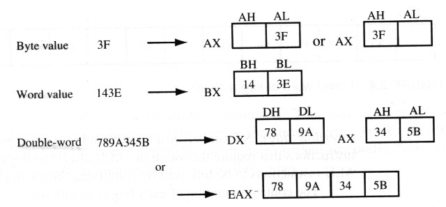
2.6
Pentium Data Organization
-
Bits , Bytes , Words (Fig
2.5)
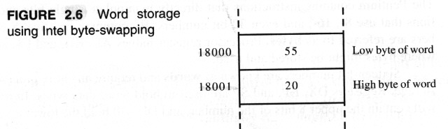
-
Byte-Swapping (Fig
2.6)
-
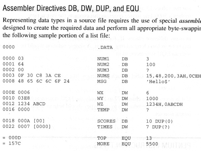
Assembler Directives (DB,
DW, DUP, EQU )
* DB : define byte
* DW : define word
* DUP : duplicate
* EQU : equate
2.7
Pentium Instruction Type
-
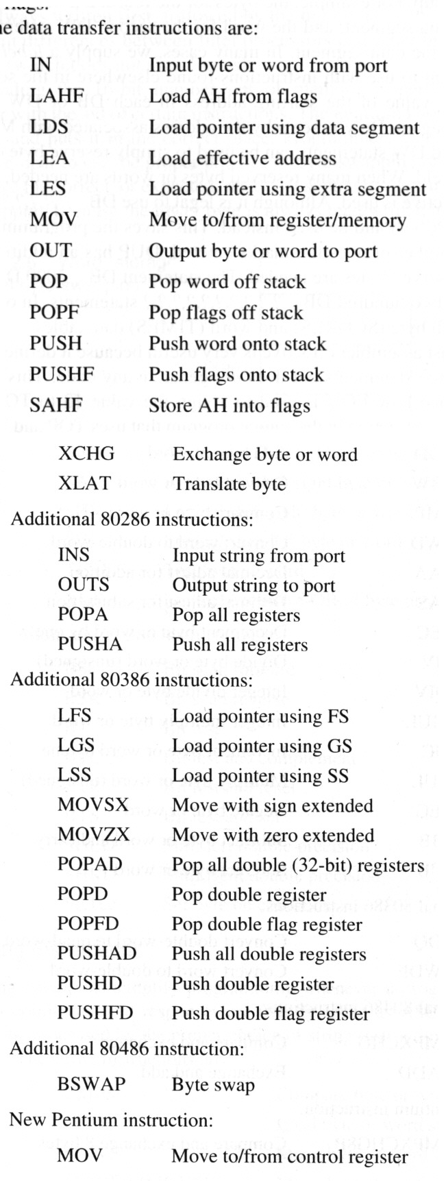
1. Data transfer instruction
(MOV)
-
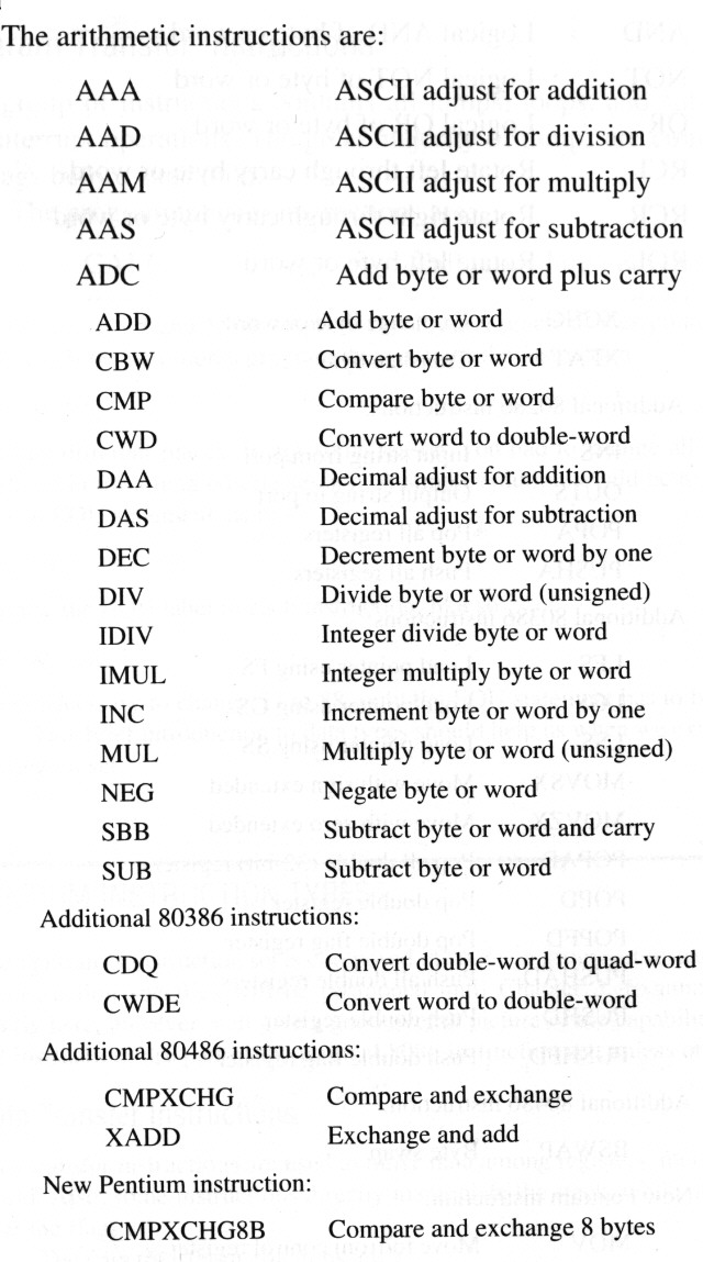
2. Arithmetic instruction
(ADD)
-
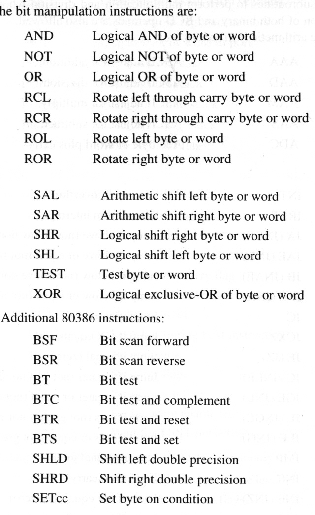
3. Bit manipulation instruction
(AND)
-
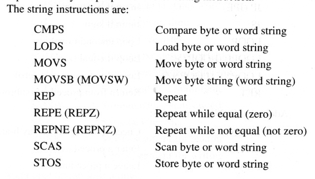
4. String instruction
(CMPS)
-
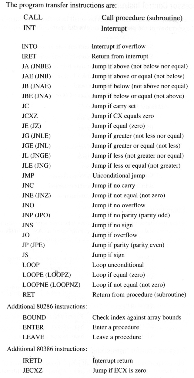
5. Program transfer instruction
(CALL)
-
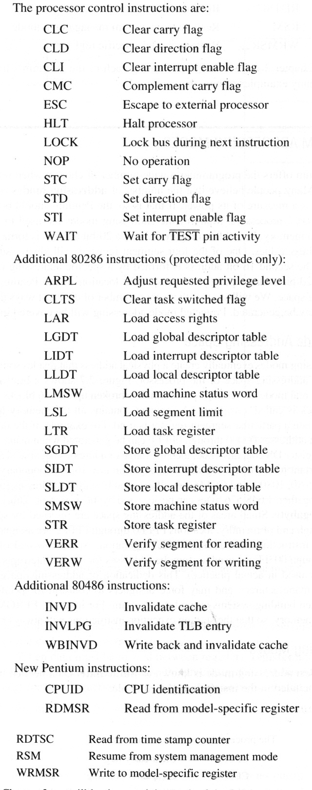
6. Processor control instruction
(CLC)
2.8
Pentium Addressing Modes
-
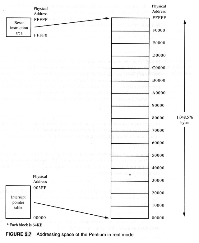
Real
Mode Addressing Space (Fig 2.7)
-
Addressing
Mode
1)
Immediate : e.g. MOV
CX,1024
2)
Register Addressing : e.g. ADD
AL,BL
3)
Memory Addressing :
* Direct : e.g. MOV
AX,[3000]
* Register Indirect : e.g. MOV
BX,[SI]
* Based : e.g. MOV
AX,[BX+4]
* Indexed : e.g. MOV
[DI-8],BL
* Based Indexed : e.g. MOV
[BP+SI],AH
* Based Indexed with Displacement :
e.g. MOV CL,[BX+DI+2080]
* String Addressing :
e.g. MOVSB (use SI & DI as pointer)
* Port Addressing :
e.g. IN AL,40
OUT 80,AL
-
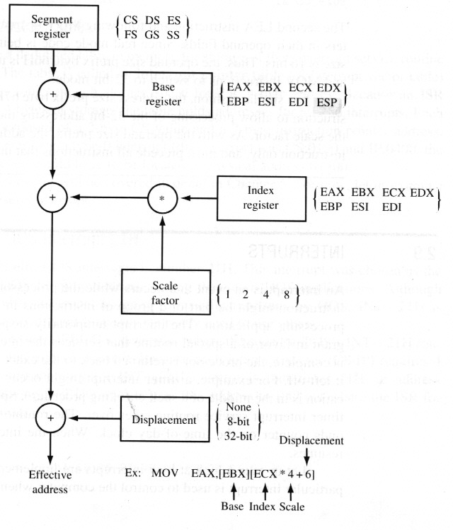
32-Bit
Addressing Mode
* Generating a 32-bit address (Fig
2.8)
* 66H : Operand size prefix byte
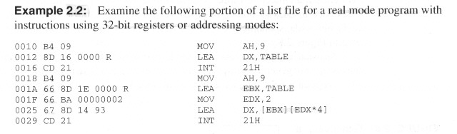
* 67H : Address size prefix byte (Exa
2.2)
2.9
Interrupts
-
Hardware
Interrupt
* NMI : nonmaskable Interrupt
* INTR : maskable Interrupt
-
Software
Interrupt
* INT 0 ~ INT 255
* INT 0 : divide error
* INTO = INT 4 : interrupt on overflow
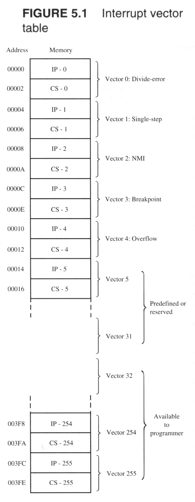
-
Interrupt
Vector Table (Fig 5.1)
* for storage ISR table
* ISP : Interrupt Service Routine
-
A
brief look at DOS INT 21H
* vector address = 21H * 4 = 84H
* ISR address ==> (-Dump) 0726:16B4
* e.g.
MOV AH,2CH ;get system time
INT 21H
;DOS call
: ENTRY : AH <== 2CH
EXIT
: CH = hrs
CL = min
DH = sec
DL = hundred of sec
2.10
The 8086 : the first 80x86 machine
2.11
A summary of the 80286
2.12
A summary of the 80386
2.13
A summary of the 80486
2.14
A summary of the pentium
2.15
Summary