Chap#6
Sequential Logic
Topic
:
-
Combination
components :
Change
input at t ,
will change output at t + td
-
Sequential
components :
*
contain memory element .
*
change input at t ,
will change
state at t + td1
output at t + td2
-
Sequential
circuit, their output depend on
the
sequence of input values
-
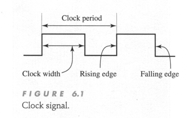
Clock
signal (
P212 )
-
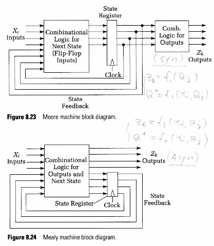
Sync seq
ckt (Moore
machine) (
F8-23R )
-
Async
seq ckt (Mealy
machine)
-
Introduce
basic storage elements
know
as latches and flip-flop
-
Analysis
procedure for seq logic
-
Establish
the finite-state-machine model
6.1
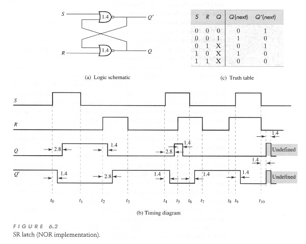
SR-Latch
-
SR-Latch ( NOR implement )
( P213
)
-
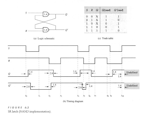
SR-Latch ( NAND implement )
( P215 )
6.2
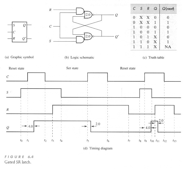
Gated SR-Latch
6.3
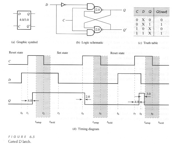
Gated D-Latch
6.4
Flip-Flops
-
Gated latches are often called
level-sensitive latches.
-
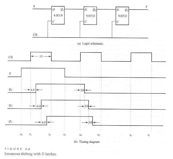
Erroneous shifting with D latches
( P220 )
-
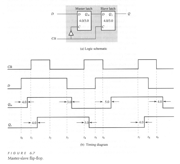
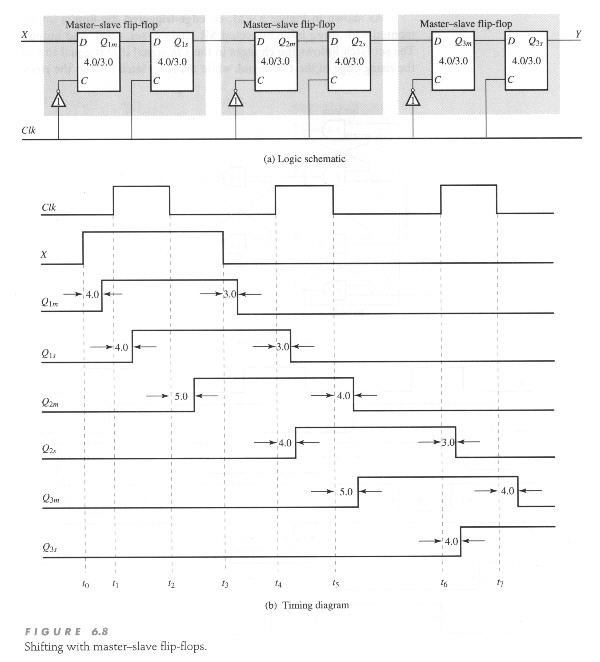
Master-Slave
flip flop (
P221 )
-
Shifting with Master-Slave flip
flop
( P223 )
-
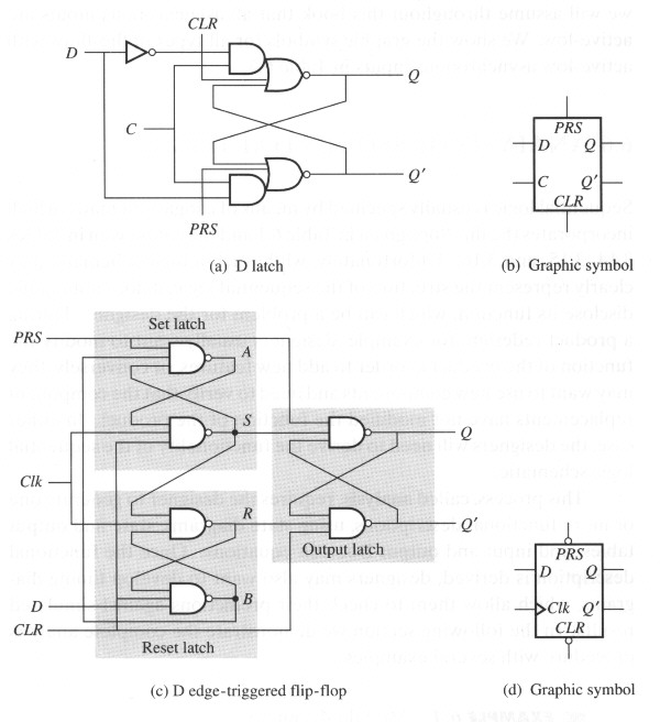
Edge-triggered
flip-flop
( P224 )
6.5
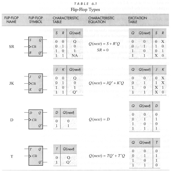
Flip-Flop types
-
Flip-Flop types
( P226 )
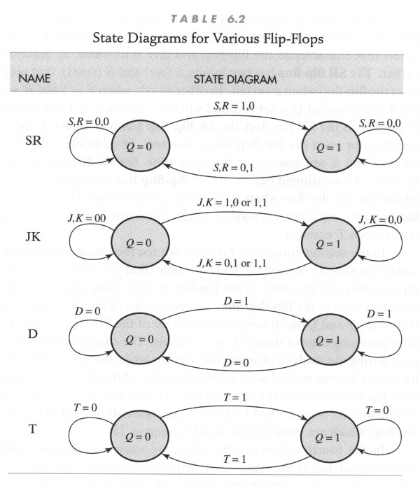
-
State diagrams for various FF
( P228 )
-
Storage elements with asynchronous
inputs
( P229 )
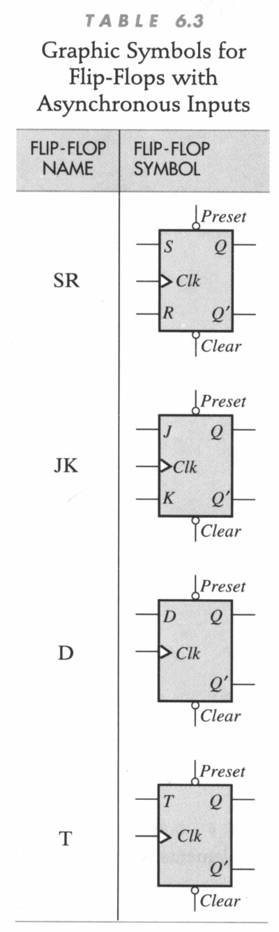
-
Graphic symbols for FF with
async. input (
P230 )
6.6
Analysis of Sequential Logic
-
e.g. 6.1 Modulo-4 counter
( P231
)
-
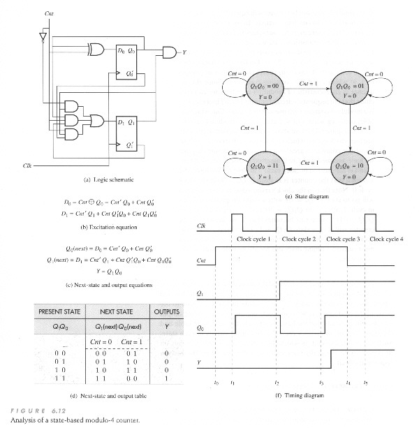
e.g. 6.2 State-based Modulo-4
counter
( P234 )
Y = Q1*Q0
( State-based or Moore-type seq ckt )
-
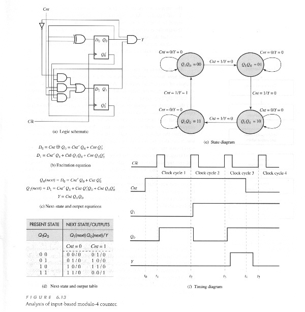
e.g. 6.3 Input-based Modulo-4
counter
( P237 )
Y = C*Q1*Q0
( input-based or Mealy-type seq ckt )
-
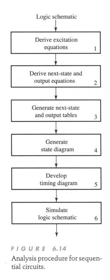
Analysis procedure for seq circuit
( P238 )
6.7
Finite-State-Machine Model
-
FSM define as quintuple
FSM
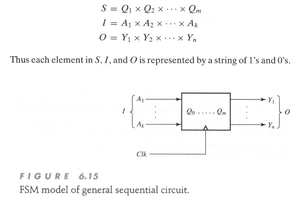
==> { S, I, O, f, h }
S : a set of state
I : a set
of input
O : a set of ouput
f : next state
function
h : output function
f : S x
I ==> S
h : S ==>
O ( state-based or Moore FSM )
h : S x
I ==> O ( input-based or Mealy FSM )
-
FSM model of general
seq ckt ( P239 )
-
FSM model of modulo-4 counter
state-based (
P240A )
input-based (
P240B )
-
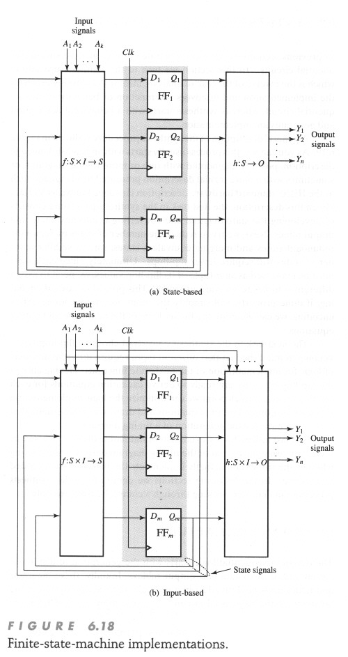
FSM Implementation
( P241 )
6.8
Synthesis of Sequential Logic
-
VHDL : IEEE Standard HDL
-
Synthesis procedure for FSM
models
( P242 )
-
FSM design procedure (quote
from Katz)
1) understand problem
2) obtain state diagram
3) state minimization
4) state assignment
5) choose FF
6) Implement
6.9
FSM Model Capture
-
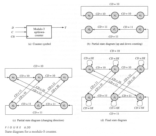
Ex 6.4 Modulo-3 up/down-counter
C : count enable
D : count direction
Y = 1, when u2;
Y = 1, when d0
up sequence : u0,
u1, u2
down sequence : d0,
d1, d2
-
State diagram for a modulo-3-counter
( P244
)
6.10
State Minimization
-
For m state, need [ log2
m] (ceiling)
-
State minimization is based
on the concept of
the behavioral equivalence
of FSMS
-
State equivalence
Sj =
Sk iff
1) same output
( h(Sj, i) = h(Sk, i) )
2) same nest
state ( f(Sj, i) = f(Sk, i) )
-
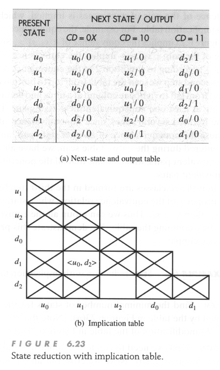
Ex 6.5 State Reduction
state reduction for
modulo-3 counter
( P247 )
Implication table
( P248
)
-
Ex 6.6 State reduction with
implication table (
P250A )
reduced state {u0, d0},
{u1}, {d1}, {u2, d2}
6.11
State Encoding
6.12
Choice of Memory Elements
-
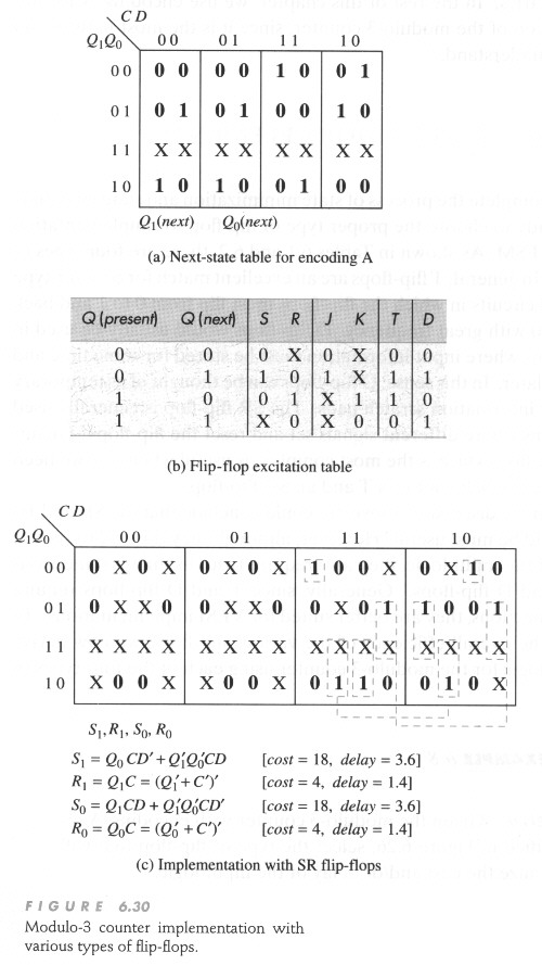
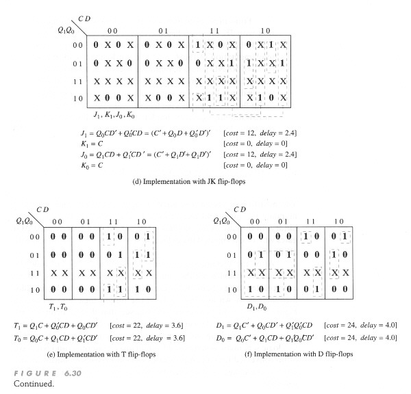
Modulo-3 counter imp with various
types of FF (
P258 ) ( P259 )
6.13
Optimization And Timing
-
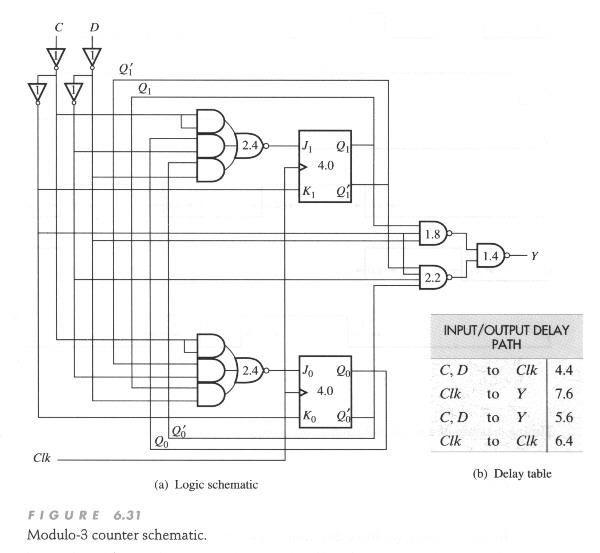
Modulo-3 counter schematic
( P261
)
-
Timing diagram of a modulo-3
counter
for a sequence of input
values
( P262 )
6.14
Chapter Summary
6.15
Further Readings
6.16
Problems
-
P6.2
P6.6 P6.9 P6.9
P6.10
P6.11 P6.12 P6.13 P6.14